Introduction:
This project was organized through three individual sprints. In each sprint we aimed to improve our project on an electrical, mechanical, and firmware basis. We mapped our project journey below, in our sprint organization format.
Sprint 1:
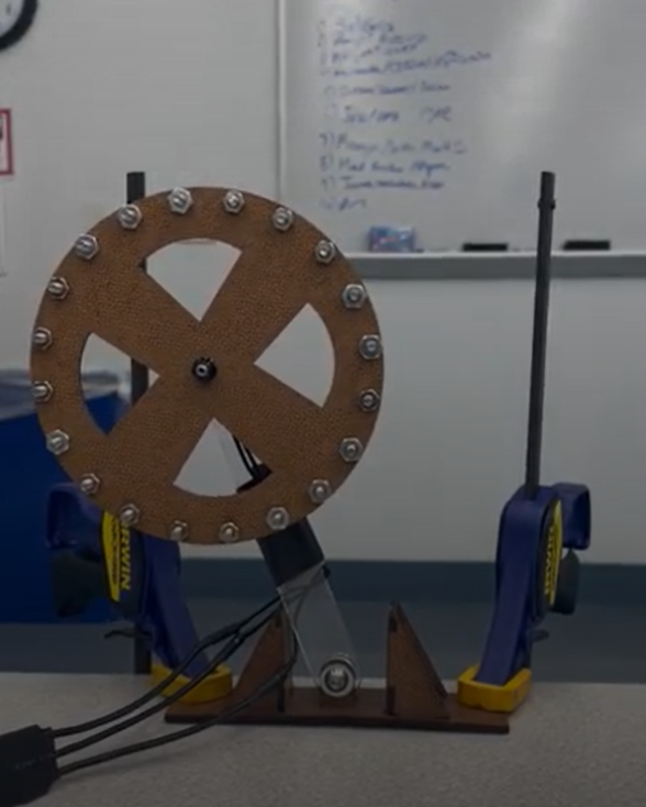
Overall:In sprint review 1, we created an iteration of an inverted pendulum, made our first electrical schematic, created the software architecture, learned control basics, started to create a timeline of the project, and understood team dynamics. This is what we demonstrated during sprint review 1→ IMG_3088.MOV
Sprint review 1 was the time when our team was still finding out how to scope and organize our project. We decided to set up a trello board for team organization and divided up our team into firmware/electrical (Ishan, Ahan, Nividh) and mechanical (Anthony and Cian). We set up milestones we wanted to hit, and based on if we hit those we’d make our project harder or easier.
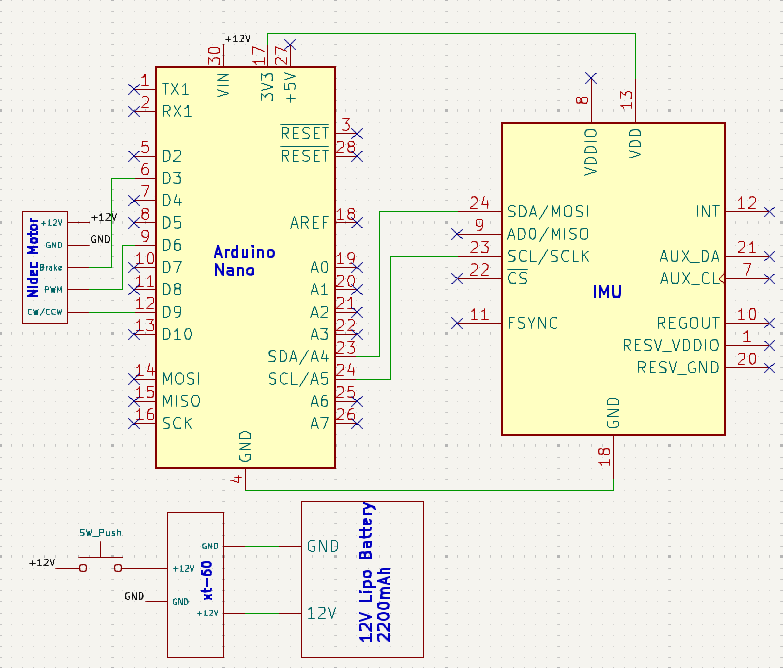
Electrical:Our goal final electrical system at the culmination of sprint review 1 looked like this:
During our initial sprint review, we created a complete electrical schematic to identify the exact components we needed. At that time, we planned to use electronic speed controllers (ESCs), but we later decided not to include them in the final cube. This change meant we also had to switch to a different type of motor, which led to significant revisions in our original design. Despite this, the fundamental approach remained sound: the Arduino would provide PWM signals to control the motor speed, while the IMU would supply accelerometer and gyroscope data for the PID loop. The system would still draw power from a 12V LiPo battery. In the demo we showed during the sprint review, the setup consisted of just one ESC and one motor, with everything else unchanged. The Arduino’s PWM output determined the flywheel’s speed, and the IMU’s sensor readings were integrated into the control logic as planned.
Firmware:For Sprint 1, we used relatively basic Arduino C++ code to control the ESC which controls a brushless motor as a servo using the Servo library. We first tested whether or not our motors had enough torque to rotate an inverted pendulum from rest to the opposite side. Since this was successful, we believed we could use the motor to balance the inverted pendulum at a setpoint. Thus, we calibrated our IMU and used accelerometer data to attempt to oscillate about the center setpoint. However, since the IMU was mounted to the same panel as the flywheel, we faced vibrations that introduced noise in the accelerometer data. At this point, we started to realize how difficult working with the IMU was going to be
Mechanical Design:In Sprint 1, the mechanical team created a simple inverted pendulum to allow the software and electrical team to test code and electronics. This inverted pendulum was essentially a test bed for electronics and code while the mechanical team worked on creating the first MVP of the cube. On the fabrication side, we opted for laser cut fiberboard and acrylic. We created a basic flywheel with a circle of fiberboard with a ring of bolts and nuts around the outside. This flywheel was around the same weight and size as the flywheels we used in the prototype and final cubes. The base it was mounted on also had small walls on either side of the pendulum to prevent it from falling too far out of its unstable equilibrium position. This way the user doesn’t need to hold the pendulum in equilibrium while testing code.
Sprint 2:
Mechanical:For sprint 2 the mechanical team was in a technical sense ahead, but we couldn’t let that slow down our progress. We designed and sized out initial versions of the cube dimensions using eucaboard. This material was chosen due to its relative abundance, and for its ease of manufacturing using a laser cutter. This facilitated rapid prototyping, and allowed us to experiment with different methods of attaching side plates together, electrical mounting, motor mounting and aesthetics. The overall assembly was pressfit with box joints. From rapid prototyping the mechanical team made critical design decisions such as having the final cube made out of metal as much as possible, seamless fitment between panels, and the ability for the cube to look like a fully enclosed metal box.
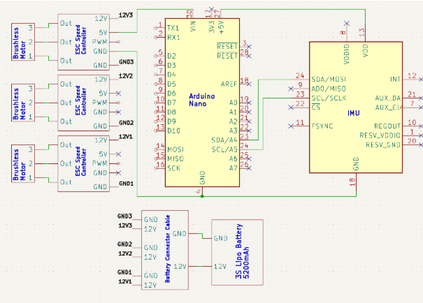
Electrical:For Sprint Review 2, our team implemented the schematic that we had designed using the parts we had on hand to attempt to balance the Eucaboard cube. We spent a lot of time on integration at this point. For example, we soldered the power wires from the ESC to the XT60 connector on the LiPo battery, and decided to power the Arduino using a 5V output from the ESC. Much of the electrical system remained the same from Sprint Review 1 to Sprint Review 2, and overall we didn’t get as far as we expected due to the motor issues we were dealing with specifically since the motors couldn’t switch directions quick enough.
For Sprint Review 2, for the Eucaboard cube, we wrote a function to calibrate/reset the ESC, and implemented the PID controller. We then attempted to tune the PID controller to return a value for the PWM output from the Arduino and used serial output to view the error our IMU was detecting and the PWM output.Finally, we tried to prevent possible errors by constraining the output to a valid PWM range and using a Kalman filter. However, since the motors couldn’t switch direction quick enough, tuning the PID loop was pretty much impossible.
Sprint 3:
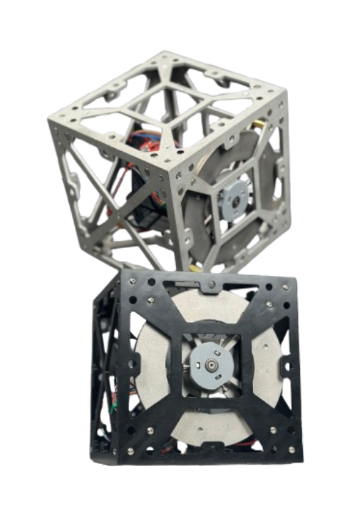
For sprint 3 the mechanical team was still much farther ahead compared to electrical and firmware, so the entire team decided to have a secondary fall back plan if balancing the metal cube didn’t seem feasible. A 3D printed version, constructed from PLA would serve as our main cube where we would test on. Key considerations were factored in when designing this 3D printed version, the ability for any key structural piece (ie. sideplates, flywheels, etc.) to be machined with metal and for each piece to have concrete manufacturing steps. Extra mounting holes were added in case our stretch goal of balancing on a corner was feasible.
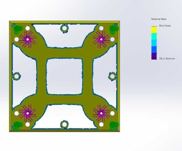
Lightweighting of plates was determined based on critical mounting points, topology studies in solidworks based on maximal motor torque exerted on mounting points, and optimization of best stiffness to mass ratio. For topology study the chosen material was 6061 AL, as it only made sense to be lightweight on the metal version, and the design would still apply for the 3D printed version. [Show solidworks topology study]
To address the mechanical’s sprint review 2 design decisions of seamless fitment, corner brackets were designed for each of the cube’s corners. These corner brackets were 3D printed using PLA and used 4-40 heat-set inserts. Iterations were needed to finalize heat set insert tolerances and promote the ease of installation. [Show corner brackets and iterations]
To mount our breadboard and electronics a 3D printed mounting plate was attached to the 3 sides of the plate. With the 3D printed version of the box IMU placement wasn’t finalized so placement would be determined with hand tooling.
The metal version of the cube was very similar to the 3D printed version, as the 3D printed version was designed with the intent of being able to be easily manufactured. Each plate started off with ⅛” thick 6061 AL sheets, these sheets would then be waterjet revealing mounting holes, lightweighting patterns and base geometry. [Show slidedeck of manufacturing (waterjet), and final pieces]
Brass standoffs were machined on a lathe and allowed for spacing for our waterjet motor mounting plates. [Image of brass standoffs]
Steel flywheels would be used on the metal cube instead of aluminum due to the metal cube’s increase of weight. Steel is naturally 3 times denser than aluminum so it was naturally the first choice when wanting to increase moment of inertia. Aluminum flywheels were used on the 3D printed cube.
The main challenge in designing a cube with seamless fitment was the corners as each edge would need to be chamfered at a 45 degree at the very tip and any imperfection would result in improper alignment of the final assembly. This would be remedied through the usage of a bolt down milling plate, with locating features precisely defined on the waterjet. Each side could be easily rotated without losing tolerance. Conversational programming of a manual mill was used to optimize the machining process.
With a system experiencing a lot of vibration due to motor oscillation, positive locking was needed on critical components. A combination of nylock nuts and spring washers were used to mitigate the effects of vibration.
In terms of aesthetics, every mounting hole was countersunk and press fit 3D printed stubs were used on existing holes to allow for small magnets to attach due to aluminum’s non-ferric nature. Thin galvanized steel plates were chosen due to its corrosion resistant coating while retaining ferric abilities. These steel plates would be used to transform our cube into a simple metal box. [Image of fully covered metal box]
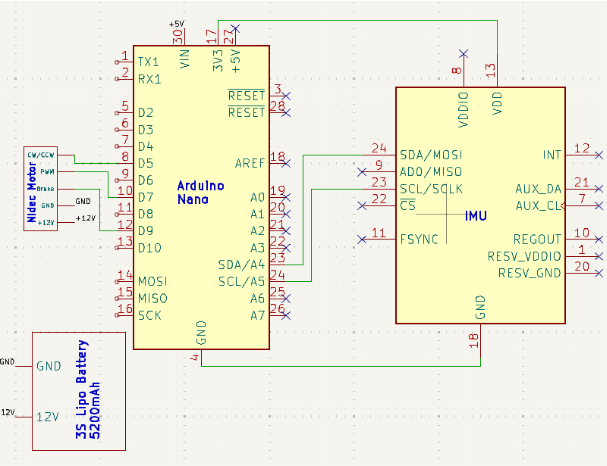
Electrical:Prior to Sprint Review 3, our Nidec motors had arrived. These had built-in drive, so no external motor drive circuit such as an electronic speed controller (ESC) would be required. They could also now switch directions quickly so more progress could be made in comparison to Sprint Review 2. Thus, we focused on integrating the Nidec motor, IMU, an Arduino Nano into the 3D printed cube. This is how the new schematic looked:
We ended up using a 12V 5A laptop charger connected to our motor using a 12V DC barrel connector instead of the LiPo battery so that we didn’t have to cyclically drain and charge our battery during the extensive testing phase. For the time being we decided to power the Arduino Nano through the USB 2.0 cable type A/B since we needed Serial communication anyways. Figuring out the wiring for our Nidec motors ended up being a much larger problem than we predicted. The motor sellers didn’t provide a datasheet, so we found one online:
However, the pin arrangement actually ended up being backwards for the motors we had bought. What was also heavily misleading was the fact that on the connector, V-/GND was blue in color while V+ was purple. On the other hand, Channels A and B were black and red respectively which intuitively makes no sense. We noticed this before actually powering any motors, so no damage was dealt.
Firmware:Sprint 3 from a firmware perspective mainly involved tuning the PID loop for the 3D printed cube. We tested out the Zielger-Nichols method, but because our system was in unstable equilibrium, it wasn’t really useful. We also used a complementary filter using both accelerometer and gyroscope data to get a more accurate angle value for a better error estimate. We then created and analyzed graphs displaying our error, proportional, integral, derivative, and output PWM values in order to better understand how to adjust our PID coefficients. One example is this graph:
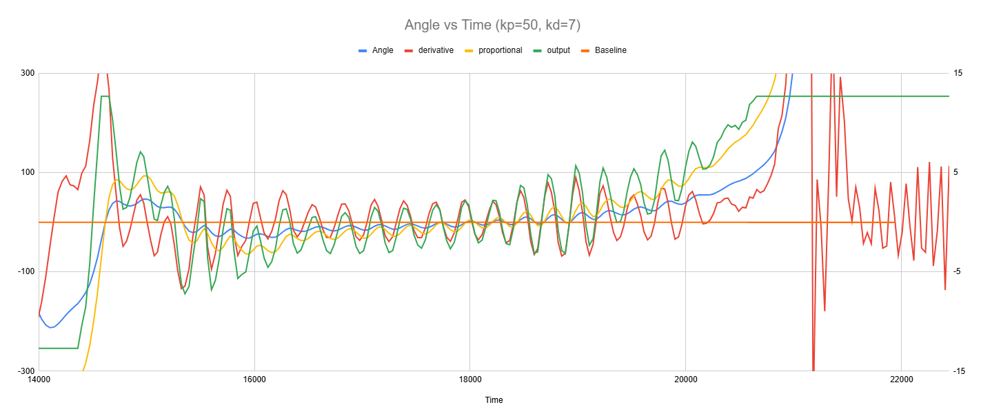
As shown in the above graph, after about 5 seconds of balancing about the setpoint, our IMU data would experience drift and the error would start to constantly increase. We learned how to deal with this problem following feedback received in our Sprint 3 Review.
Leading to Demo Day:
After finishing up all the mechanical and electrical work by the end of sprint three, we focused entirely on PID tuning, filtering IMU measurements, and finalizing our firmware in the weeks leading up to Demo Day. During this time, we fully integrated the system and got everything working together.
One of the biggest challenges we faced was solving the drift issue that was preventing our cube from balancing. In sprint three, we were using a complementary filter, however since this was heavily dependent on the gyroscope input (which drifted) to function we needed to pivot. So, we switched to the Madgwick filter using the Arduino IDE's Madgwick library. This change made a big difference—it helped us filter out the drift and finally get the IMU readings stable enough to work with. However, to make this filter effective, we had to reposition the IMU. Previously, the cube was rotating around the yaw axis, and the Madgiwick filter would’ve required factoring in magnetometer data to correct the drift. However, this would likely cause issues due to the electromagnetic field created by the brushless motor. Instead, by moving the IMU so the cube rotated around the pitch axis, we solved the problem.
Once the filtering was sorted, we dove into tuning the PID values. We used a mix of the Ziegler-Nichols method and trial-and-error to dial it in. Another problem we faced was that we weren’t sending outputs to the motor quick enough for it to correct errors. This was solved by implementing a timer-driven execution loop and stopped serial printing. Thus, we optimized our output transmission and control. After getting everything working on our plastic cube prototype, we re-tuned our constants for the metal cube and unconstrained the PWM outputs. With the math and control strategies implemented in the firmware, we tested and tweaked until the metal cube finally balanced.